Machine design is the process of developing a machine or piece of equipment into a complete unit ready for manufacture. The end result is a 3D model, working and assembly drawings, and documentation that enables the machine shop to manufacture the machine and the manufacturer to demonstrate that it meets safety requirements. The designer’s actual work involves balancing these requirements: functionality, safety, manufacturability, cost, and maintainability often pull in different directions, and a good solution adequately meets all of them.
A poorly defined problem can easily lead to a machine that is well-designed but wrong. That is why the designer makes the most important decisions before opening the CAD program.
Machine design, mechanical design and equipment design – what is the difference?
In practice, these terms overlap, and many people use them interchangeably. Roughly speaking, they differ by level: machine element design is the component level, machine design is the level of the functional whole, and mechanical design is an umbrella term that runs through them all. The meaning of equipment design varies by industry.
| Term | What is designed | Typical output |
|---|---|---|
| Mechanical design | Umbrella term: all mechanical structures, from components to complete devices | 3D models, working and assembly drawings, and structural analysis as needed |
| Machine design | The entire machine: moving parts, drive systems, controls, and safety as a single system | Drawing package and documentation demonstrating conformity, such as the risk assessment and technical documentation |
| Equipment design | In the process industry, a static process device, such as a tank, pressure vessel, or heat exchanger. In product development, a user-oriented product that combines mechanics, electronics, and software | In the process industry: equipment drawings, data sheets, and procurement specifications. In product development: product specifications, prototypes, and manufacturing documentation |
| Machine element design | Individual machine elements, such as shafts, bearing arrangements, gears, bolted and welded joints, and springs | Design calculations, component drawings, and selection of standard parts |
Equipment design is the vaguest of these terms. In the process and energy industries, it is distinguished from piping and layout design, and in plant projects, it can also refer to the selection and specification of equipment. What both meanings have in common is that the equipment does not necessarily involve significant movement or power transmission of its own.
Machine element design focuses on strength, fatigue, tolerances and fits, materials and the selection of standard parts. It is usually a sub-task of machine design rather than a separate service. Adding to the confusion, machine design is also the name of a field of study in mechanical engineering, in which case it also covers machine elements and strength of materials.
At Hefmec, machine and equipment design is part of mechanical design, and, if necessary, we design the entire machine and its individual components within the same project. A more detailed explanation of this concept can be found in the article mechanical design.
How does a machine design project progress?
Projects range from a single jig to an entire production cell, but the designer almost always makes decisions in the same order. The third column of the table shows that risk assessment is not just one step among many, but rather runs throughout the entire project.
| Step | What the designer decides | Role of risk assessment | Result |
|---|---|---|---|
| 1. Requirements | Intended use, capacity, loads and utilization rate, operating environment, interfaces, maintenance and cleaning, production volume, and cost target | Limits of the machine: intended use, reasonably foreseeable misuse, users, and life cycle stages from installation to dismantling | Requirements specification, e.g. URS |
| 2. Concept | 2–3 operating principles in parallel; comparison based on performance, risk, manufacturability, maintainability, cost, and schedule | Preferably a solution in which no hazard arises at all | Selected concept and preliminary cost estimate |
| 3. Detailed design | Structure, components, materials, tolerances | Guards and safety functions, as well as the level of reliability required of them, which guides the design of the control system | 3D model |
| 4. Dimensioning | Load cases, manual calculation or FEM, fatigue, and buckling | Fault conditions and foreseeable misuse result in load cases | Structural analysis calculations |
| 5. Drawings and review | Working and assembly drawings, manufacturability review | Solutions that reduce risk are shown in the drawings | Production-ready documentation |
| 6. Compliance | Compiling the technical documentation | Finalizing the risk assessment and documenting residual risks | Risk assessment, technical documentation, content of the instructions for use |
| 7. Manufacturing and commissioning | Manufacturing, assembly, testing | Verification that the safety functions work | Operational machine, user manual, and the manufacturer’s declaration of conformity |
The first phase is often the most critical. Once the need has been carefully documented—for example, in a user requirements specification (URS)—the designer knows what the solution must be dimensioned for, and changes in later stages are minimized. During the concept phase, it’s not worth going into detail on the first viable idea right away. Comparing two or three alternatives takes a few days, but the wrong operating principle can wipe out the entire project budget.
The EN ISO 12100 standard describes the steps in risk assessment: defining the boundaries of the machine, identifying hazards, estimating risks, and reducing risks. The designer reduces risk in this order: first through structural solutions, then through guards and safety functions, and only as a last resort through operating instructions and warnings. The later a hazard is identified, the more often the only remaining option is a guard or a warning label.
The machine manufacturer conducts a risk assessment, compiles the technical documentation, and signs a declaration of conformity before affixing the CE marking to the machine. Machinery Regulation (EU) 2023/1230 replaces the Machinery Directive 2006/42/EC and will apply starting January 20, 2027.
Manufacturability is determined at the design stage
It is advisable to consider manufacturability as early as the concept phase. If the designer does not consider the welding sequence, accessibility of machined surfaces, or assembly sequence until the working drawings are prepared, changes to the structure will be required at a stage when they are already time-consuming and costly. The designer should review at least the following:
- Welded structures: Welding heat distorts the structure. For this reason, machine shops typically machine the precise mating surfaces only after welding is complete, and the designer selects the welding sequence so that deformation remains under control.
- Surfaces to be machined: The way the workpiece is clamped during machining and the tool’s access to the surface determine how many clamping operations and machining steps the part requires.
- Standard components: A ready-made bearing housing, linear guide, or cylinder is often cheaper, available more quickly, and easier to replace than a custom part.
- Assembly: The design determines the order in which parts can be installed. If a screw cannot be accessed after assembly, it cannot be maintained either.
- Transport and installation: The designer divides a large machine into modules that have lifting points and that fit within transport dimensions and through the doorways at the installation site.
Ismo Lehtinen, Project Manager at Valmet Automotive, describes our joint preliminary design project as follows: “Hefmec carried out a preliminary design project for us that defined the welding processes for manufacturing the entire golf cart chassis. As a follow-up project, they also supplied us with welding jigs. The project began with preliminary design and led to a project delivery. We worked closely with Hefmec and our product design team, which allowed us to design the product to be as manufacturing-friendly as possible.”
Structural analysis as part of the design process
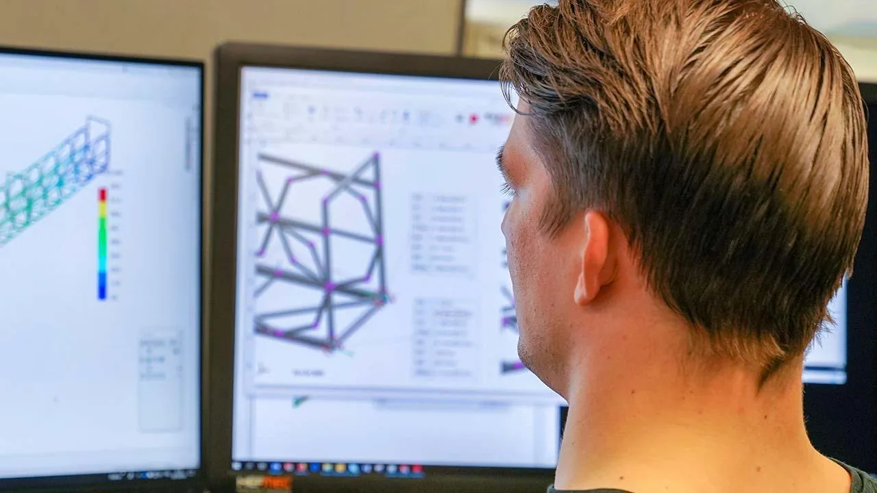
Structural analysis is not a review of a finished model but rather part of the design process. Before the designer performs any calculations, they define the load cases: normal use, extreme conditions, transportation and installation, and foreseeable failure scenarios. An incorrectly selected load case produces an accurate answer to the wrong question.
Manual calculations are often sufficient for beams, joints, and shafts, and they quickly provide an order of magnitude against which FEM results can be compared. FEM analysis is useful for complex geometries, examining stress concentrations, and when the designer is lightening the structure. However, FEM alone does not make a structure safe: the quality of the results depends on the model, the boundary conditions, the loads, and whether the analyst can distinguish between actual stress peaks and those caused by the model.
In a welded structure subjected to repeated loading, fatigue often governs the dimensioning before static strength does, and for slender structures, the designer must also check for buckling. The basics can be found in the article “What is structural analysis?”, and we perform structural analysis and FEM analysis as part of the same project alongside the design work.
Materials and tolerances – costs are determined in the drawing
A designer does not select a material based solely on strength. Weldability, machinability, corrosion resistance, operating temperature, availability in standard sizes, and price are equally important factors. Stronger steel does not automatically result in a lighter or cheaper structure: if fatigue is the determining factor in the design, changing the steel grade will not significantly improve the strength of a welded joint, but welding may become more difficult.
Tolerances largely determine the cost of manufacturing a part. A tolerance that is too tight increases manufacturing costs without providing any functional benefit, while one that is too loose causes assembly, operational, or service life problems. The designer limits tight tolerances to surfaces critical to function and checks the tolerance chains—that is, where deviations in individual parts accumulate during assembly.
Maintainability and life cycle
The machine will be in use for years, so maintainability should be addressed during design rather than later at the plant. The designer ensures that wear parts can be replaced without disassembling the rest of the structure, that areas requiring inspection are visible and accessible, and that standard components can be used as replacement parts. In cleanrooms and the food industry, this also includes cleanability: the structure must not have any areas where dirt can accumulate.
Common mistakes in machine design
| Mistake | Consequence |
|---|---|
| Detailed design before the requirements are locked | Each change affects multiple drawings |
| Skipping the concept phase: the first idea straight into detail design | A better operating principle can only be found when implementing it is expensive |
| Considering manufacturing only in the working drawings | Extra rounds of drafting, costly work steps, and deformation during welding |
| Copying tolerances from previous drawings | Manufacturing costs rise without any functional benefit |
| Relying on FEM results without evaluating loads and boundary conditions | The structure is over- or under-designed, even though the calculation appears accurate |
| Forgetting maintenance clearance and installation | Replacing a wear part requires disassembly, and installation is delayed |
| Addressing safety only after the structure is complete | Only guards and warnings remain, and they slow down use |
Examples of Hefmec’s machine design
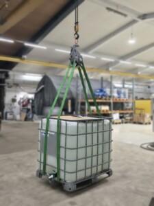
We design both new machines and modifications and upgrades to existing equipment. One of our customers in the engineering industry needed a way to lift and rotate a spherical product during various stages of production. With the lifting accessory we developed, the customer can handle heavy and awkwardly shaped workpieces safely, efficiently, and consistently, and all stages of the process can be carried out using the same tool.
Other examples of our projects:
- valve pressure testing rig
- welding jig for vehicle battery plate parts
- lifting and turning accessory for a ball valve ball
- mechanical design of a mobile maintenance bridge
- steel structures supporting production equipment
- format part trolley suitable for cleanrooms
When it comes to an entire production cell or line, the design process extends to specialized machinery and production cells, which we can also supply as a turnkey solution.
When does it make sense to outsource machine design?
Outsourcing typically makes sense when in-house design capacity is insufficient, the schedule is tight, or the task requires expertise that isn’t available in-house, such as structural analysis or CE documentation. An external designer also provides an independent perspective: we review a design or concept created by someone else before the client commits a manufacturing budget to it. When modernizing an old machine, we assess which parts of the structure should be retained and which should be replaced.
You can purchase design assistance on a flexible basis—whether for the entire project or just one phase, even for as little as a day. Let us know your needs, and we’ll work with you to determine the best place to start.
Frequently asked questions
How much does machine design cost?
The price depends on the scope of the project, the stage at which the designer becomes involved, and how complete the requirements specification is. We also offer daily rates for short, limited tasks, such as preliminary and conceptual design or structural analysis: 680 € + VAT per day (2026), for tasks lasting 1–5 days. A single jig takes a few days or a few weeks to complete, while an entire machine takes weeks or several months. You’ll get the most accurate estimate when you tell us your needs and schedule.
Who is responsible for the CE marking if we purchase the design from Hefmec and have the machine manufactured elsewhere?
The manufacturer of the machine—that is, the party that places the machine on the market—is responsible for the CE marking, not the designer. We prepare a risk assessment and technical documentation for the manufacturer’s use, enabling the manufacturer to issue a declaration of conformity based on them. If we supply the machine ourselves, we are also responsible for the CE marking. When the supplied assembly is only part of a machine to be assembled later (partly completed machinery), the manufacturer prepares assembly instructions and a declaration of incorporation into the final machine instead of a CE marking.
Will we be able to use the results of the design for our own purposes?
Yes. We provide 3D models and drawings in the agreed-upon format, so you can have the machine manufactured at the machine shop of your choice or continue the design work yourself.
Still have questions?
Tell us about your machine or equipment needs, and we’ll work together to figure out how to get started. Learn more about Hefmec’s mechanical and machine design services, or contact Product Manager Juho Seppälä directly at +358 50 525 7504.